GENG2004 - Lecture 5
Measuring Mechanical Properties - Slides
Measuring Mechanical Properties
-
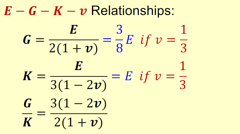
@ Review: Elastic Properties of Materials
-
! Slides explain how these constants are found through experiments
Experimental Measurement
Material constants are obtained through testing:
- Tensile/compression test →
- Shear/torsion test →
- Hydrostatic compression →
As an engineer, it is important that we understand how these properties are obtained, as in the future if you are using a new material, you will need to be able to determine its properties through experimentation.
Skills you will need as an engineer:
- Designing experiments intentionally
- Keeping them simple (1 variable ideally)
- Knowing all your variables:
- Independent variables
- Dependent variables
- Controlled variables
Static and Dynamic Loading Conditions
- Static loading slow, constant application of load
- Dynamic loading very fast application of load
- Time which the sample is loaded is comparable with time of elastic wave propagating through the sample
- Size is known
- Wave propagating velocities are known
- Time which the sample is loaded is comparable with time of elastic wave propagating through the sample
- ! Materials behave differently depending on loading speed
Characteristic Points of Stress-Strain Curve
Recap: Understanding Deformation Behaviour & Mechanical Properties
- True stress actual cross-sectional area of sample used to find stress
- Shrinks during loading, more physically accurate
- Nominal stress initial cross-sectional area of sample used
- Used in solving problems
Through deformation of most material, the true stress will shrink as necking occurs; you can observe this in photographs in the slides
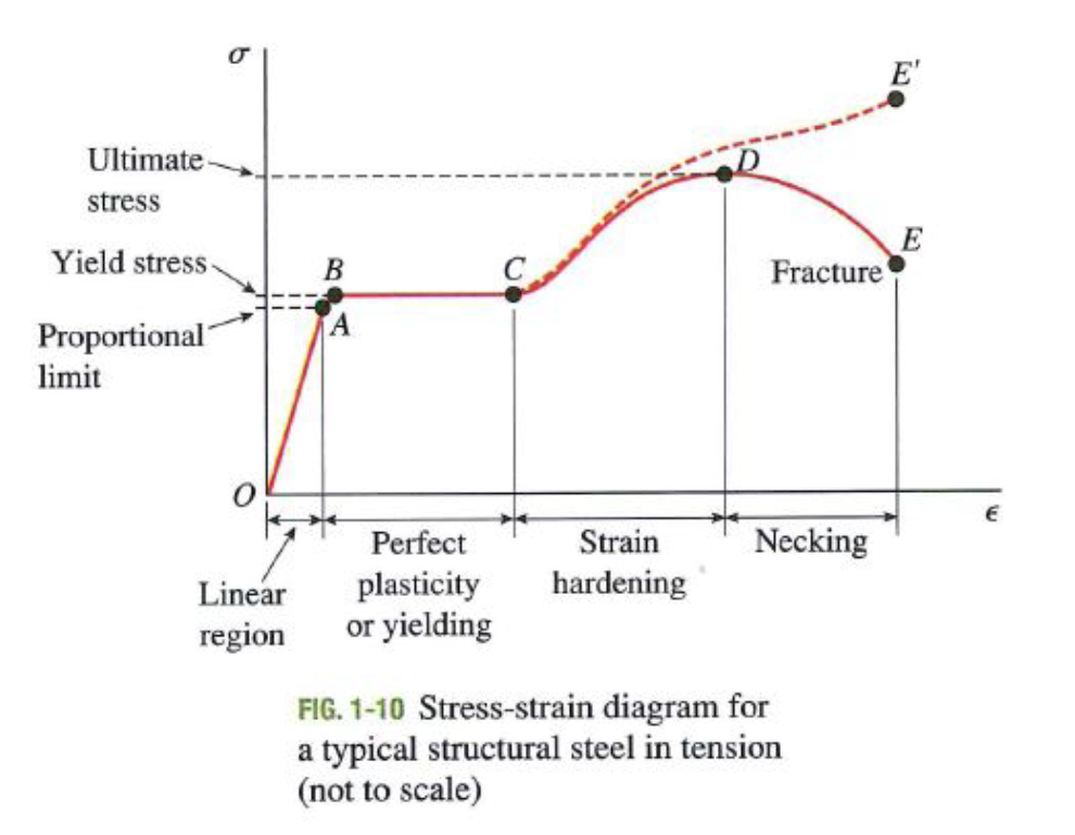
- OA linear elastic region
- Straight (linear) line
- Stress strain
- This is the area where Hooke’s Law applies
- Slope of OA is the Young’s Modulus
- Past this point, equations fail
Point A proportional limit
-
Beyond A, proportionality between stress and strain no longer exists
-
AB non-linear region (elastic → plastic transition)
- Curve bends
- Material starts behaving differently internally
- Some part still elastic, some part permanently deformed
Point B Yield Point
-
The corresponding value of stress is known as yield stress
-
Yield stress = yield strength → we do not want to exceed this point
-
BC perfectly plastic region (yielding)
- Strain increases, stress stays constant
- Material is deforming without extra load
-
CD strain hardening
- Stress increases again
- Crystalline structure changes
- Increased resistance of material to further deformation
Point D Ultimate stress
- Maximum stress reached → known as ultimate strength
- Further stretching → results in failure at point E or E’
- Necking occurs reducing area significantly
- Fracture point is known as failure stress
In real engineering design, we must ensure:
This is to avoid permanent deformation
As engineers, we can use the curve in order to choose an appropriate material depending on the circumstance:
- The curve indicates both strength (yield stress) and stiffness (slope)
Offset Method
- Some materials have no clear yield point
- However, they have initial linear region
- An arbitrary yield stress may be determined using the offset method
Method:
- Take linear elastic slope
- Shift it right by a small strain:
- Where new line intersects the curve → offset yield stress
Elastic vs Plastic Behaviour
- Elastic limit is the max stress a material can withstand without experiencing permanent deformation
- Elastic limit usually same or slightly above proportional limit
- Plasticity ability of a material to undergo permanent deformation
- Plastic flow occurs when large deformations occur in a ductile material loaded into the plastic region
- Material structure permanently changes
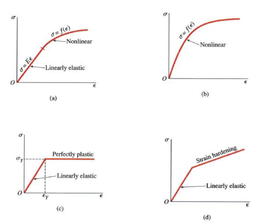
Non-linear Behaviour
-
Stress-strain curve depends on the material
Creep
- Stress/strain also depends on time
- Recap: ENSC1004 - Creep
- Strain increases overtime under constant stress
Relaxation decrease in stress over time under constant strain
Fatigue
- Fatigue is failure due to repeated loading cycles
- Material can fail at stresses much lower than ultimate stress
- Shown using a -N curve: stress vs # of cycles
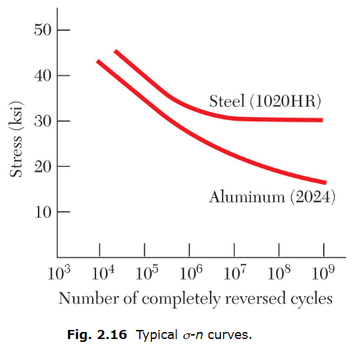
- Endurance limit is the stress for which failures do not occur
- Even for indefinitely large number of loading cycles
- Recap: Failure by Fatigue
Materials such as aluminium and copper have no endurance limit meaning they will always fail eventually