Enable (Gated) RS Latch
- Additional Enable input signal C is used:
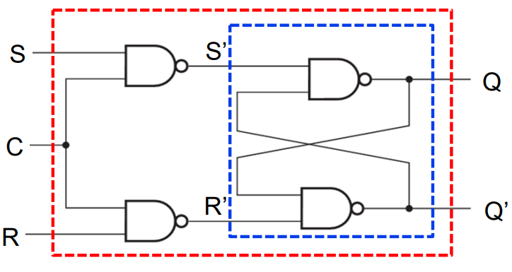
- Dotted blue area is the RS latch from last lecture
- Control input acts like an enable
- When C=0, latch remains in same state
- When C=1, normal latch operation occurs
An enabled latch is a level sensitive memory output may change a number of times depending on the duration of the enable pulse
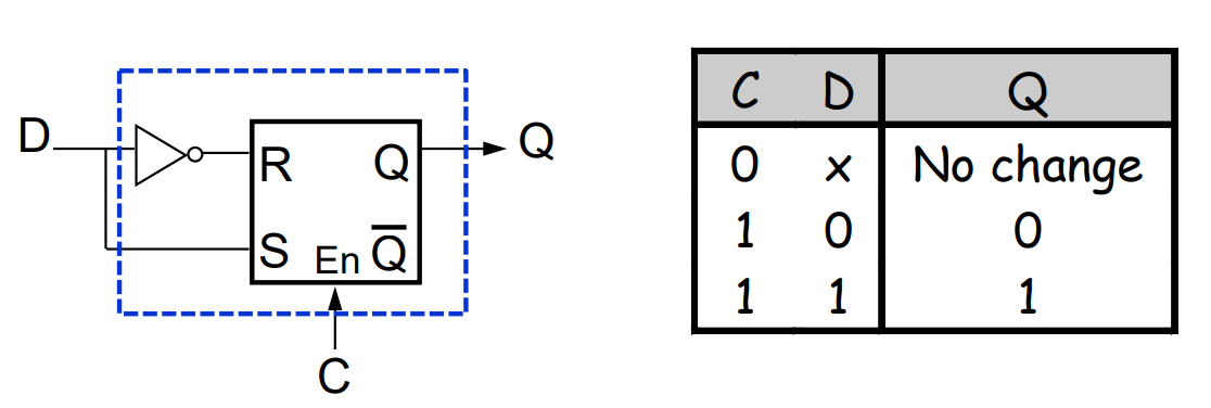
Enabled (Gated) D-Latch
- One data input
- S=D and R=D’
S R
- S=D and R=D’
Clocks and Flip-Flops
- For proper operation, latches must form flip-flops
- They can change state only at well defined times
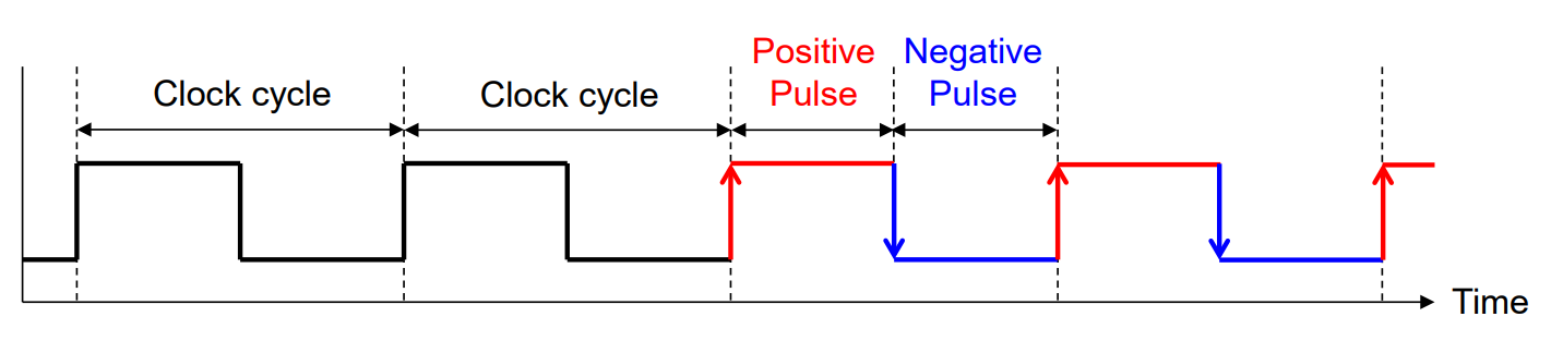
- Clocks are often used to synchronise circuits
- They generate repeating, predictable pattern of 0s and 1s
- If several circuits share a common clock signal, they can coordinate their actions with respect to one another
Master Slave D Flip-Flop
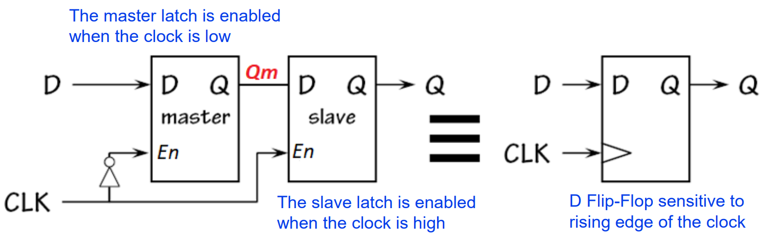
- Structure two D-latches connected in series
- The master latch is connected to the input D
- The slave latch is connected to output Q
- Controlled by inverted signal controlling master latch
- One latch is enabled at any given time
- The final output changes during one transition of clock
Edge-Triggering
- Edge-triggering means the output change can happen only during clock pulse transition
- Noted using a triangle symbol
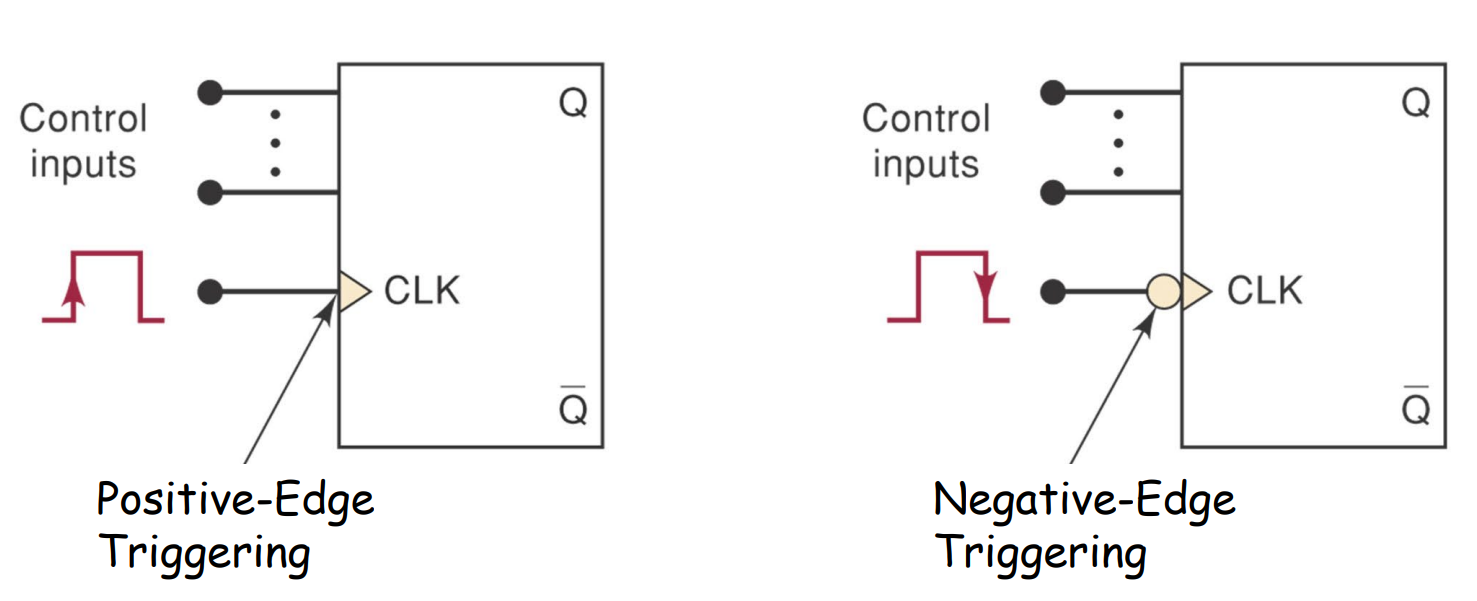
- Two types: (see slides for diagrams)
- Positive edge-triggering output looks at input at the instant the clock transitions from low to high
- Negative edge-triggering output looks at input at the instant the clock transitions from high to low
Flip-flop Variations
- There are many different flip-flops based on the D flip-flop
- Flip-flop examples:
- JK flip-flop inputs are used to complement current state
i.e. JK = 1 → current content is flipped- Otherwise works as RS latch
- T flip-flop only maintain or complement its current state
i.e. T = 1 → current content is flipped- Otherwise no change
- JK flip-flop inputs are used to complement current state
- Characteristic tables on slides