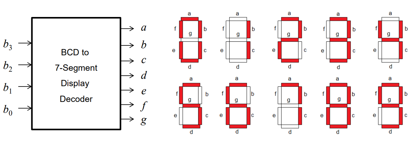
BCD to 7-Segment Display Decoder
- A 7-segment display is made up of seven individual LEDs
- Each LED labelled from a-g
- Commonly found in digital clocks
- The output of a decoder determines which LED segments are on
Encoders
- Encoders are combinational circuits that perform opposite function of a decoder
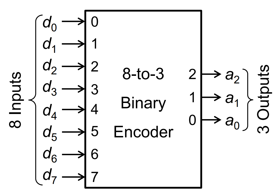
- Generates an output binary code for the active input
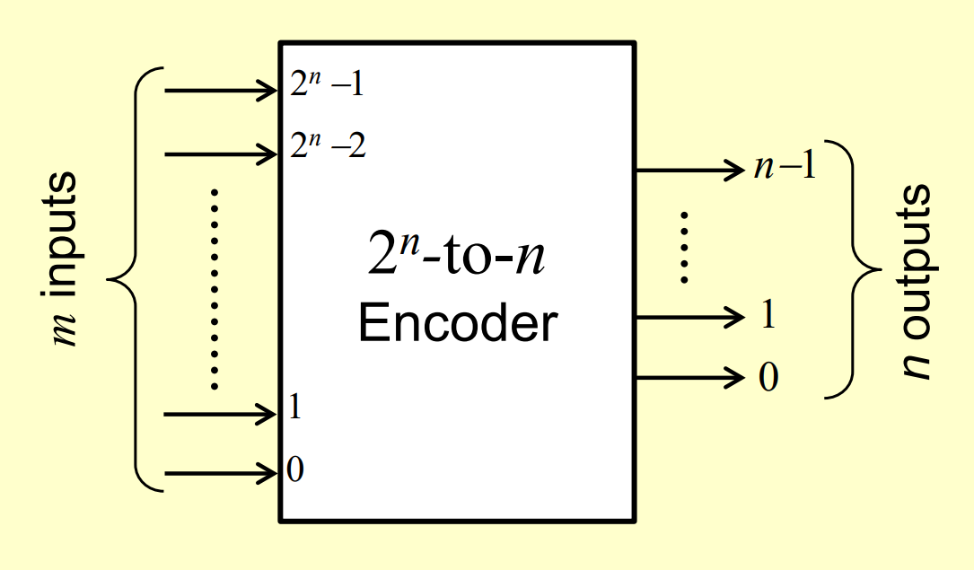
- For correct operation, requires that only a single input line is asserted at any one time
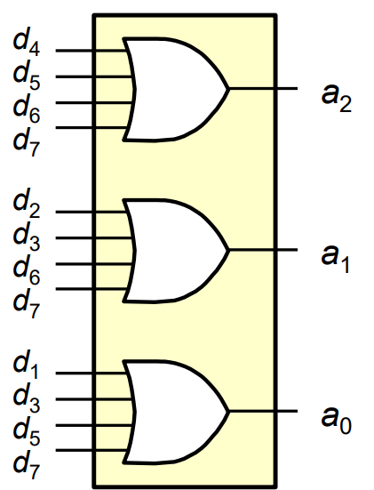
- Simple encoders can be made with just OR gates:
Limitations
- We assume only a single input line can be active at any time
- Having more than one input can create undesired outputs
- If no inputs are active, then the output is 000… which should usually only occur for when
Priority Encoder
- A priority encoder can be used to solve the above two issues
A priority encoder works through:
- Assigning priority to inputs
- Only encoding the highest priority active input
- Introducing an extra output to indicate whether all inputs are inactive
Decoder Applications
- Used when an output or group of outputs are to be activated only on the occurrence of a specific combination of input levels
- Used widely in memory
- They respond to input address code to active particular memory location
Encoder Applications
- Encoder converts information into some coded form
- e.g. convert calculator number input into binary code
Memory
- Three properties to be considered memory:
- Holds values
- Able to read saved values
- Able to change saved values
- One-bit memory holds a single bit, 0 or 1
Storage
- Using loops, circuit outputs become inputs
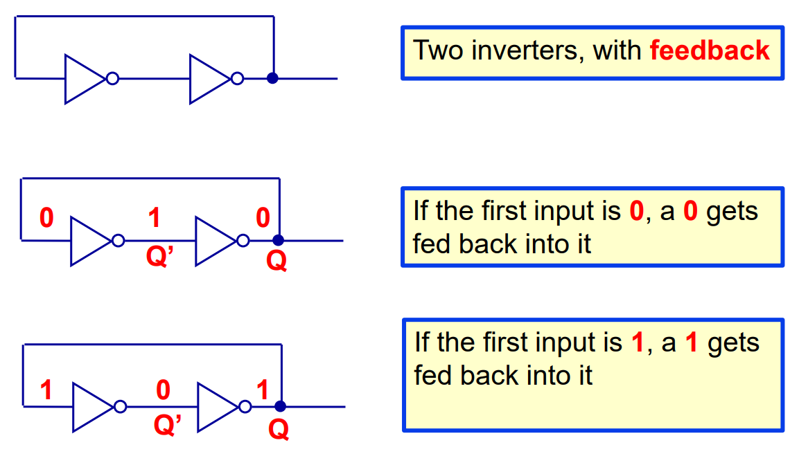
- Still extra steps needed to be considered memory
- We cannot change the value in the loop!
RS Latch
- Using NOR gates instead of inverters allows us to make a RS latch
- RS → Reset-Set
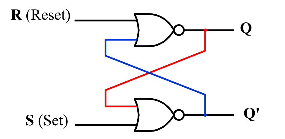
- The two inputs R and S let us control outputs Q and Q’
- Q and Q’ feed back into the circuit
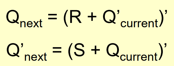
- Q and Q’ feed back into the circuit
Set Operation: RS = 01
- S → 1 → 0 → 1
i.e. set Q to 1 - Outputs then stop changing
- Circuit becomes stable
Reset Operation: RS = 10
- R → 1 → 0 → 1
i.e. reset Q to 0 - Outputs then stop changing
- Circuit becomes stable
Remember, there is propagation delay for all these changes
- R=S=1 should never be used
RS Latches are Memory
- RS latch meets all of our criteria above to be considered memory
- The output Q is considered the state of the latch
- Represents the data stores