Synchronous Sequential Circuits
- Synchronous sequential circuits use a clock signal
- Clock determines when memory updated
- See Clocks & Flip-Flops
The Clock
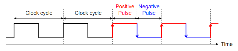
- Clock cycle (or period) is a time duration
- Clock frequency = number of cycles per second (Hertz)
- Clock frequency = 1 / Clock Cycle
Circuit Timing
- Until now → we focused on circuit functionality
- But what about timing?
- How fast can a circuit go?
- What happens if a circuit runs too fast?
Real signals do not change instantly:
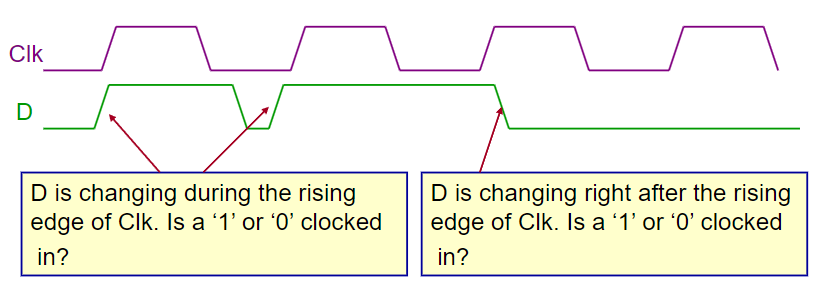
- ! A circuit that works logically may not work in real-world practice
Flip-Flop Parameters
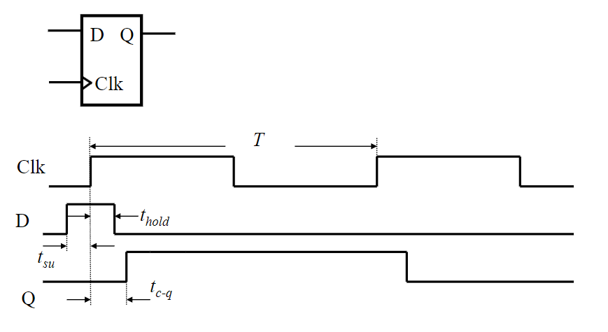
- → setup time that input must be stable before arrival of clock edge
- → hold time that input must be stable after clock edge
- → propagation delay from clock edge to output change
If setup/hold constraints are violated → output is unreliable
The input needs to be stable before and after the clock pulse
Metastability
- Synchronisation failure occurs if input changes too close to clock edge
- Not likely in practice
- Output becomes undefined (not 0 or 1) → unstable
- Eventually settles, but may yield incorrect value
Dealing with Synchronisation Failure
- Probability of failure can be reduced (but not to 0):
- Slow down system clock
- Use faster flip-flops (smaller setup/hold)
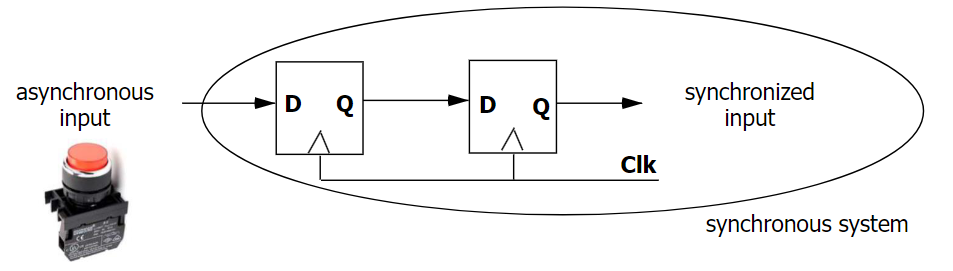
- Synchroniser chain → cascade two (or more) flip-flops:
- For metastability to propagate, both flip-flops have to fail
- ! Adds latency, increases power consumption and chip area
Timing Constraints
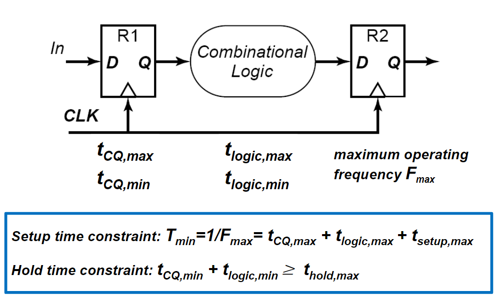
From an input change → propagation delay (CQ) → logic gates → setup
- Imagine a signal passing through this segment of the circuit
- All of these steps need to occur before the next clock cycle
- Worst-case path for setup = longest delay path
Identify the longest logic path in your circuit, as if you can meet it’s setup time constraint, all other logic paths should also work
Ensure input doesn’t change too soon
- Prevent data corruption immediately after clock edge
- Worst-case path for hold = shortest delay path
- We can add inverters to a circuit to increase the delay and prevent a hold time violation
Here, we instead want to identify the shortest logic path in our circuit
When checking both of these constraints, we need to ensure we choose a clock cycle that fits our entire circuit. Flip-flops and gates may all have different hold/setup/gate times, and thus we need to identify the longest and shortest logic path in our circuit carefully.
Pipelining
- Pipelining is a technique used in digital design to increase the speed of synchronous digital circuits
- Divide complex process → process smaller stages in parallel
- Using memory to pipeline the system enables new operations to start before the old ones are completed
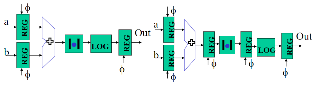
As seen in the diagram, outputs can be held in registers allowing components to execute new operations on new inputs
In the first circuit, our is from our three components. However using pipelining, now each component is its own ‘step’ and we reduce to only !
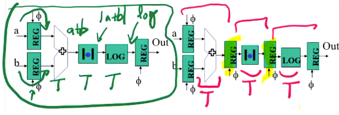
Thus we have reduced the setup time constraint!