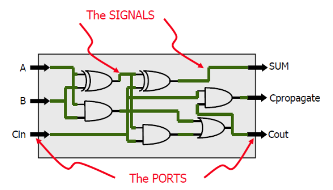
Modern chips have millions to billions of transistors and it would take too long to design circuits by hand. Instead, we write code to describe what the hardware should do. These specialised computer languages are known as hardware description languages (HDL).
Very High Speed Integrated Circuit HDL, also known as VHDL, is mainly used for FPGA designs. It is important to note that VHDL is not a programming language; hardware operates simultaneously as opposed to sequentially.
A VHDL file comprises of at least 3 fundamental sections:
Architecture− internal behaviour/implementation of entity
Basic Syntax
VHDL is a free format language
No formatting conventions, such as spacing or indentation
Not case sensitive
Each VHDL statement must be terminated by a ”;”
The file extension for a VHDL file is .vhd
Comments
Comments in VHDL are indicated with ”—”
e.g. ‘—main subcircuit’
Libraries and Packages
Library is a collection of commonly used pieces of code
LIBRARY library_name;
USE library_name.package_name.package_parts;
IEEE 1164 − Package STD_LOGIC_1164
In basic digital logic theory, a wire can only be 0 or 1
In practice, this doesn’t reflect how real wires behave
e.g. distortion or electrical interference can impact signals
STD_LOGIC gives us access to 9 values for our logic system
Better captures real world conditions
To use STD_LOGIC:
LIBRARY ieee;USE ieee.std_logic_1164.all;
We can also use STD_LOGIC_VECTOR to model groups of wires acting together, (e.g. an 8-bit data bus)
SIGNAL a : STD_LOGIC; -- 1 wireSIGNAL b : STD_LOGIC_VECTOR(7 DOWNTO 0); -- 8-wire bus
Each element can independently be any of the 9 unique values
STD_LOGIC_VECTOR is useful as we can quickly manipulate groups of related bits as one object
Use a single quote to hold a single bit signal: a <= '0' ;
Use a double quote to hold a multi-bit signal: b <= "00" ;
Standard VHDL Operators
Logical (e.g. AND, NOR, XOR, NOT, etc.)
Relational (e.g. =, >, <=, etc.)
Arithmetic (e.g. + and -) for type INTEGER
Signal Assignment Operator <=
General form of a signal assignment statement is:
target <= expression;
Target is a signal that receives the values of the expression
e.g. z <= a NAND b; indicates that the value of signal z represents the NAND of signals a and b
Context tells you the meaning of <=
Sequential vs Concurrent Statements
There are two types of statements in VHDL. Sequential statements are found in a process whereas concurrent statements are found outside a process.
Sequential statements evaluate sequentially in terms of simulation. However, processes are evaluated concurrently (i.e. more than one process can be active at any given time).
Input Ports can only be read, but they cannot be assigned a value
Output Ports can only be assigned a value, but they cannot be read
Signal Properties
Each SIGNAL can be used multiple times. We can connect a wire to one or multiple loads. Each SIGNAL is global to its ARCHITECTURE.
Signal Assignment Operator <=
<= has a different meaning depending on whether it is inside or outside a PROCESS construct:
In both cases, <= schedules a signal update
Outside a PROCESS, the concurrent assignment is re-evaluated when one of its input signals changes
Inside a PROCESS, it means schedule an assignment at the end of the process
Signal vs Variable Assignments
If you assign a value to a signal within a process, it will only update after that process has executed. For example, in this attempt of writing the ARCHITECTURE for a multiplexer:
ARCHITECTURE function_arch OF my_circuit IS SIGNAL X : integer RANGE 0 to 3;BEGIN PROCESS(A, B, I0, I1, I2, I3) X <= 0; IF A = '1' THEN X <= X + 1; END IF; IF B = '1' THEN X <= X + 2; END IF; CASE X IS WHEN 0 => F <= I0; WHEN 1 => F <= I1; WHEN 2 => F <= I2; WHEN 3 => F <= I3; END CASE; END PROCESS;END function_arch
There is a serious issue in that all assignments of the signal X will not update until the process is resolved. The value of X used in the process will be whatever it was set to in the last instance of the process, which we have no way of determining.
This means that the function will provide unexpected results. Instead of using SIGNAL X : integer RANGE 0 to 3, we must define X as a variable —> VARIABLE X : integer RANGE 0 to 3.
VARIABLES can update mid-process unlike SIGNALS but you must assign their value using := instead of <=. Additionally, you must define your variable inside the process block as variables only exist locally within a process!
Implicit Memory
Signals in VHDL do not need to be assigned a value on every possible execution path of a combinational process. Instead, synthesis may infer a latch to retain its previous value known as implicit memory.
This simplifies creation of memory in logic design. However, this also poses the disadvantage of unwanted latches being generated when all of the options in a conditional sequential statement are not specified.
To avoid the generation of unexpected latches, you must assign every output in a combinational process through complete conditional branches or default assignments. Alternatively, cover all alternatives in a CASE statement.
const current = dv.current();if (current && current.file.tags.some(t => t.toLowerCase() === "#topic")) { const inlinks = current.file.inlinks; // Split backlinks: general notes vs. lecture notes const lectureLinks = inlinks.where(l => l.path.includes("/Lecture Notes/")); const otherLinks = inlinks.where(l => !l.path.includes("/Lecture Notes/")); if (otherLinks.length > 0) { dv.header(4, "Links To This Page"); dv.list(otherLinks); } if (lectureLinks.length > 0) { dv.header(4, "Referenced In Lecture Notes"); dv.list(lectureLinks); }}