After defining our ports in the Entity, we can add functionality to our gate:
ARCHITECTURE model OF nand_gate ISBEGIN z <= a NAND b;END model;
Now our gate has the intended functionality of a NAND gate. Multiple architectures can be created for a particular entity.
Declaration
The declaration section of the ARCHITECTURE can contain:
SIGNAL declarations → signals represents wires or states
CONSTANT declarations → constants are fixed ‘SIGNAL values’
COMPONENT declarations → allow for hierarchical design
Statement Area
This is where you define the functionality of your circuit. It is bounded by BEGIN and END statements:
ARCHITECTURE arch of my_circuit IS-- Declaration Area --BEGIN-- Statement Area --END arch;
VHDL Modelling Style
We can describe the way an architecture is designed by three coding styles: dataflow, behavioural or structural modelling. The distinction between them is based on the type of concurrent statements used.
In practice, you would use all three of these design styles as they are mainly used for categorisation than as strict guidelines.
Not all valid code written in VHDL is synthesizable. Code written in dataflow and structural modelling is always synthesizable. However, when using behavioural modelling, it depends on the synthesis tool.
Structural Modelling
Structural design involves connecting pre-built components together. You can connect multiple smaller VHDL design units into a larger hierarchical design. Hierarchy simplifies design description and makes it easier to re-use parts of your design in other projects.
Component Declaration
Components must be declared before being instantiated in the concurrent statements area.
The port list should match the port list of that component’s ENTITY declaration. The component name does not need to be the same as defined in its ENTITY, however it must then be bound to that ENTITY using a configuration.
Instead of defining a component in the declaration section of the ARCHITECTURE, we can instead define it in a package declaration. Items declared in this package can be made visible within any ARCHITECTURE body by using the library and use clauses.
Each component has a unique label to avoid naming conflicts. PORT MAP connects the actual signals in design to the ports of the instantiated component.
Full VHDL for Example Circuit
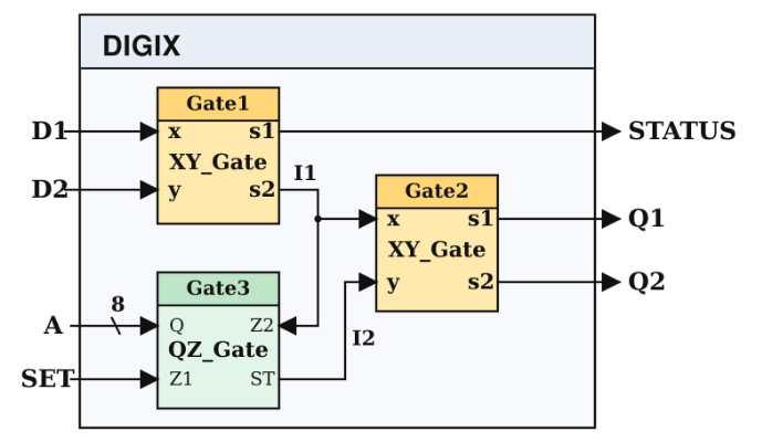
LIBRARY ieee;USE ieee.std_logic_1164.all;Entity DIGIX isPort (D1, D2, SET : in std_logic;A :in std_logic_vector(7 downto 0);Q1, Q2, STATUS :out std_logic);end DIGIX;Architecture implementation of DIGIX issignal I1, I2 : std_logic;component XY_gate IS port(X, Y: in std_logic; s1,s2:out std_logic);end component;component QZ_gate ISport( Z1, Z2 : in std_logic; Q :in std_logic_vector(7 downto 0); ST: out std_logic);end component;beginGate1:XY_Gate port map(x=>D1, y=>D2, s2=>I1, s1=>STATUS);Gate2:XY_Gate port map(x=>I1, y=>I2, s1=>Q1, s2=>Q2);Gate3:QZ_Gate port map(Z2=>I1, Z1=>SET, Q=>A, ST=>I2);End implementation;
Note: you must remember to declare your signals, such as I1 and I2 in the circuit above, e.g. SIGNAL I1, I2: STD_LOGIC.
BEGINGate1:XY_Gate PORT MAP(x=>D1, y=>D2, s1=>STATUS, s2=>I1);Gate2:XY_Gate PORT MAP(x=>I1, y=>I2, s1=>Q1, s2=>Q2);Gate3:QZ_Gate PORT MAP(Z1=>SET, Z2=>I1, Q=>A, ST=>I2);END arch;
Positional Association Connectivity
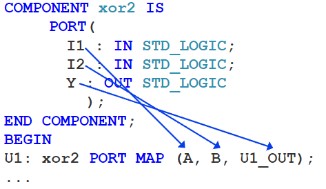
This is an alternate way to write your PORT MAP:
This method is not recommended, but is good to know as it may be used by others.
Dataflow Modelling
Dataflow modelling involves writing equations to describe the flow of data through a circuit. This is done by using one or more concurrent signal assignment statements, e.g. ‘<=’.
Dataflow modelling works well for small and relatively simple circuits. It builds circuits from scratch and allows us to see how our logic might be synthesised.
Concurrent Statements
Simple concurrent signal assignment: (<=)
Conditional concurrent signal assignment: (when-else)
Selected concurrent signal assignment: (with-select-when)
Conditional Concurrent Signal Assignment
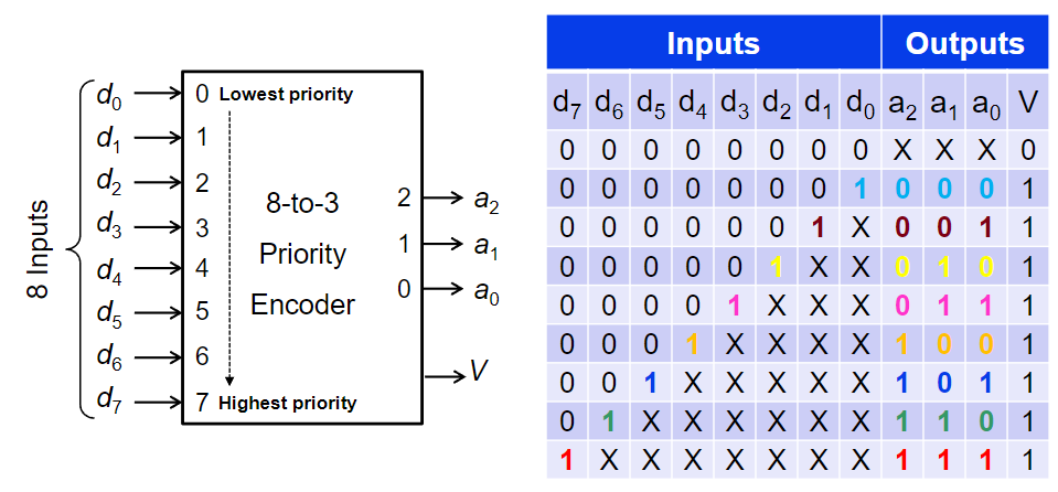
An 8-to-3 priority encoder receives eight request inputs (d0-d7), each assigned a priority. If one or more inputs are asserted, it outputs the 3-bit binary index (a2a1a0) of the highest-priority asserted input.
Implementation using when-else signal assignments:
architecture arch of priority83 isbegin a <= "111" when d(7) = '1' else -- highest priority "110" when d(6) = '1' else "101" when d(5) = '1' else "100" when d(4) = '1' else "011" when d(3) = '1' else "010" when d(2) = '1' else "001" when d(1) = '1' else "000"; -- d0, or none active V <= '0' when d = "00000000" else '1'; end arch;
Note: the when-else statements are concurrent -> meaning they all run in parallel. Reordering the statements has no effect on the circuit.
architecture arch of mux41 isbegin Y <= d0 when S = "00" else d1 when S = "01" else d2 when S = "10" else d3 when S = "11" else 'X'; -- unknown/undriven S surfaces as 'X' end arch;
As seen above, when-else signal assignments are also useful for implementing multiplexers, demultiplexers and tri-state buffers.
Selected Concurrent Signal Assignment
We can also use with-select-when assignments to implement components such as multiplexers and decoders.
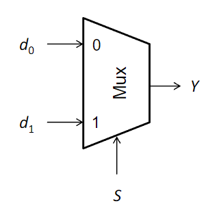
It is easiest to see how they work using a basic 2-to-1 multiplexer implementation:
architecture behavioural of mux2to1 isbegin with s select Y <= d0 when '0', d1 when '1', 'X' when others; end behavioural;
As we can see, we can select a different assignment depending on the value of our signal s. This also means that no two choices can overlap and all possible values for smust be covered unless an OTHERS choice is present.
const current = dv.current();if (current && current.file.tags.some(t => t.toLowerCase() === "#topic")) { const inlinks = current.file.inlinks; // Split backlinks: general notes vs. lecture notes const lectureLinks = inlinks.where(l => l.path.includes("/Lecture Notes/")); const otherLinks = inlinks.where(l => !l.path.includes("/Lecture Notes/")); if (otherLinks.length > 0) { dv.header(4, "Links To This Page"); dv.list(otherLinks); } if (lectureLinks.length > 0) { dv.header(4, "Referenced In Lecture Notes"); dv.list(lectureLinks); }}