Digital Systems - Home
ELEC2311 - Lecture 0
Introduction - Slides
Recap
What is a Digital System?
- A digital system takes in digital values and then outputs digital values
Digital Systems use Binary Values
- Each binary digit (called a bit) is either 1 or 0
- Bits have no inherent meaning
- Binary is popular because:
- Transistors, the basic digital electric components, operate as switches (on/off) using only two voltages (high/low)
- Storing/transmitting one of two values is easier than three or more (e.g., loud beep or quiet beep)
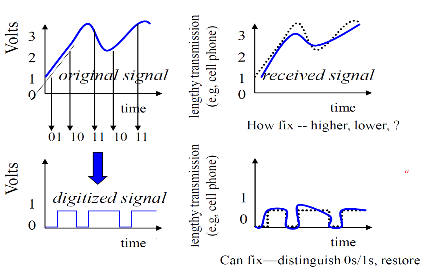
Link to originalBetter Noise Immunity
Voltage Thresholds and Logic Values
Senders and receivers need an agreed-upon mapping between voltage levels and logical signals so that they can communicate with each other
We have a voltage range specifically defined as 0 and 1
- e.g. zero-2.5 V → 0, 2.5-5 V → 1
However what if the receiver sees the voltage is around 2.5 V? Does it interpret the signal value as a logical 0 or 1?
- We don’t want a 0 to be mistaken for a 1 or vice versa
We need to account for noise which can distort electrical signals- To eliminate such confusion, we prescribe a forbidden region that separates the two valid regions and outlaw “close calls”
Thus, a voltage in this forbidden region is not a valid voltage
Link to originalThe highest input voltage value that a digital device must recognize as a logical 0 is called the low voltage threshold
The lowest input voltage value that a digital device must recognize as a logical 1 is called the high voltage threshold
Noise Margins
- Noise margins act as a safety buffer to prevent an incorrect interpretation of a signal due to noise
- We want as high a noise margin as possible
Key Voltages Used by Digital Circuits
- The lowest output voltage value that a digital device can produce when it outputs a logical 1
- The highest output voltage value that a digital device can produce when it outputs a logical 0
- The lowest input voltage value that a digital device must recognize as a logical 1
- The highest input voltage value that a digital device must recognize as a logical 0
If the noise on a line is less than the noise margin, the circuit will still correctly detect the signal. However, if the noise is larger than the margin, the circuit may misread a 0 as a 1, or vice versa — leading to logic errors.
Noise Margin Low the amount of noise a low signal can tolerate before becoming undefined
- is the low voltage threshold of the receiver
- is the voltage output low of the sender
Noise Margin High the amount of noise a high signal can tolerate before becoming undefined
- is the voltage output high of the sender
- is the high voltage threshold of the receiver
Static Discipline
- Static discipline is the concept that if you feed a valid logic level into a digital circuit, the output will also be a valid logic level
That means:
- If you give a valid low (0) or valid high (1) to a gate,
- It will output a valid low or high,
- Even if there is some noise in the signal
Link to originalTo satisfy static discipline, you must meet two requirements:
- Noise margins must be non-negative:
- If inputs meet valid input thresholds, then the system must guarantee its outputs will meet valid output thresholds:
A valid low input should always produce a valid output voltage; and a valid high input should always produce a valid output voltage (see slides for full explanation)
Note: that a device that receives an invalid input does NOT have to produce a valid output
Field Programmable Gate Arrays (FPGA)
- FPGA is a multipurpose, integrated circuit
- Device-wide programmability
- We will be using this in the unit