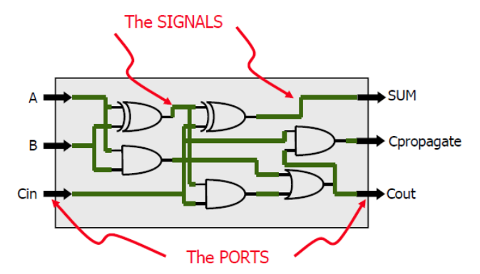
Input Ports can only be read, but they cannot be assigned a value
Output Ports can only be assigned a value, but they cannot be read
Signal Properties
Each SIGNAL can be used multiple times. We can connect a wire to one or multiple loads. Each SIGNAL is global to its ARCHITECTURE.
Signal vs Variable Assignments
If you assign a value to a signal within a process, it will only update after that process has executed. For example, in this attempt of writing the ARCHITECTURE for a multiplexer:
ARCHITECTURE function_arch OF my_circuit IS SIGNAL X : integer RANGE 0 to 3;BEGIN PROCESS(A, B, I0, I1, I2, I3) X <= 0; IF A = '1' THEN X <= X + 1; END IF; IF B = '1' THEN X <= X + 2; END IF; CASE X IS WHEN 0 => F <= I0; WHEN 1 => F <= I1; WHEN 2 => F <= I2; WHEN 3 => F <= I3; END CASE; END PROCESS;END function_arch
There is a serious issue in that all assignments of the signal X will not update until the process is resolved. The value of X used in the process will be whatever it was set to in the last instance of the process, which we have no way of determining.
This means that the function will provide unexpected results. Instead of using SIGNAL X : integer RANGE 0 to 3, we must define X as a variable —> VARIABLE X : integer RANGE 0 to 3.
VARIABLES can update mid-process unlike SIGNALS but you must assign their value using := instead of <=. Additionally, you must define your variable inside the process block as variables only exist locally within a process!
Architecture − Declaration
The declaration section of the ARCHITECTURE can contain:
SIGNAL declarations → signals represents wires or states
CONSTANT declarations → constants are fixed ‘SIGNAL values’
COMPONENT declarations → allow for hierarchical design
Architecture − Statement Area
This is where you define the functionality of your circuit. It is bounded by BEGIN and END statements:
ARCHITECTURE arch of my_circuit IS-- Declaration Area --BEGIN-- Statement Area --END arch;
Sequential vs Concurrent Statements
There are two types of statements in VHDL. Sequential statements are found in a process whereas concurrent statements are found outside a process.
Sequential statements evaluate sequentially in terms of simulation. However, processes are evaluated concurrently (i.e. more than one process can be active at any given time).