Signed Overflow
- When working with -bit signed numbers, the range of values is:
e.g. for a 4-bit system, the range is from -8 to +7 - Overflow occurs when result of a sum/subtraction is outside the range
- Only occurs when terms are both positive or both negative
- Gives incorrect result
- Overflow only occurs in two situations:
- If you add two positive numbers and get a negative result
- If you add two negative numbers and get a positive result
Sign Extension
- Sign extension is where we assume numbers have an infinite number of 0s in from of them
- Helpful for lining up decimal numbers
- However, you must be careful in extending signed binary numbers because the leftmost bit is the sign and not part of the magnitude!
- The proper way to extend a signed binary number is to replicate the sign bit, so the sign is preserved
Two’s Complement Adder
We can use a series of full adders to do subtraction
- To find A - B:
- Complement each bit of B
- Set the adder’s carry in to 1
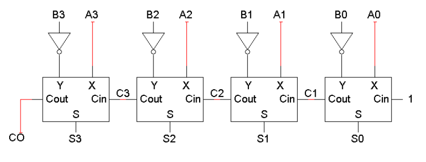
- Only differences between adder and subtractor circuits are:
- The subtractor has to negate B3 B2 B1 B0
- The subtractor sets the initial carry in to 1, instead of 0
Adder-Subtractor Circuit
- Building upon this idea, we can use XOR gates instead of inverters
- Lets us switch between add and subtract mode
i.e. A + B → A - B
- Lets us switch between add and subtract mode
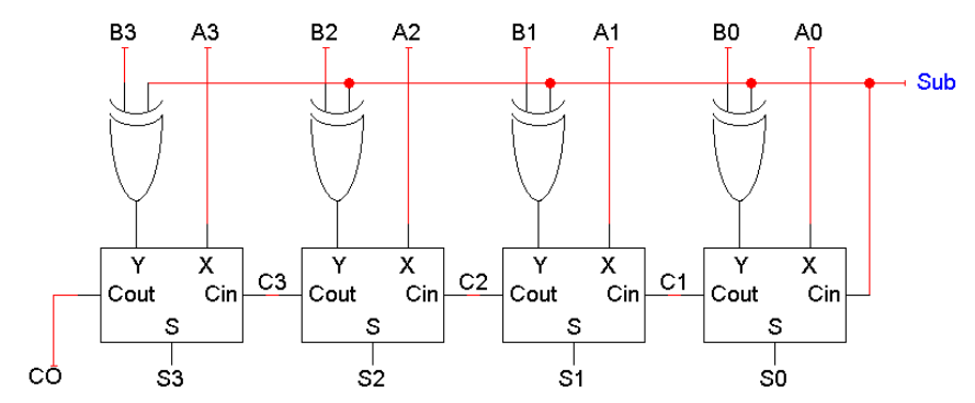
- When Sub = 0, circuit is in adder mode
- When Sub = 1, circuit is in subtractor mode
Comparators
- Comparators checks if bits are equal (A = B)
- Composed of XNOR gates to check any number of bits
- Compare each digit of two terms with the XNOR gate, then AND all the outputs
Binary Multiplication
- Binary multiplication: 1x1=1, otherwise = 0
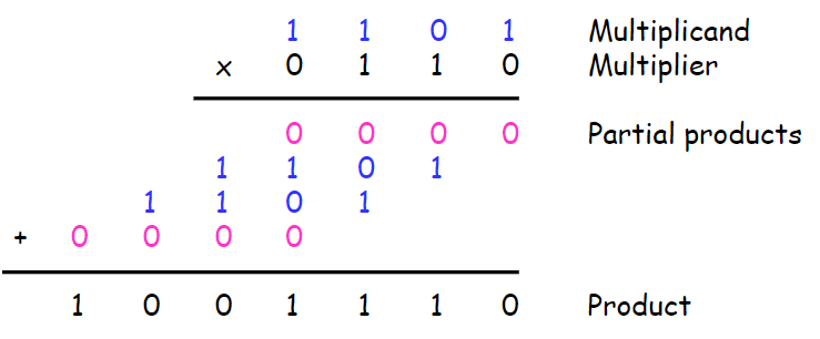
- Multiplication consists of two steps:
- Evaluation of partial products
- Accumulation of the shifted partial products
- Since we always multiply by either 0 or 1, the partial products are always either 0000 or the multiplicand (1101 in this example)
Multipliers are very complex circuits (see slides)
Shifting Bits
- Shifting bits to the left (e.g. 101 → 1010) results in multiplication
- Shift by -bits is multiplication by
- Shifting bits to the right (e.g. 100110 → 10011) results in division
- Shift by -bits is division by
4-Bit Combinational Shifter:
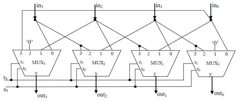
- Settings for :
- 00 → pass through
- 01 → shift left and fill with 0
- 10 → shift right and fill with 0
- 11 → rotate right
i.e. inininin → inininin
Shift Registers
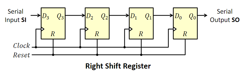
- A shift register is a cascade of flip-flops sharing the same clock
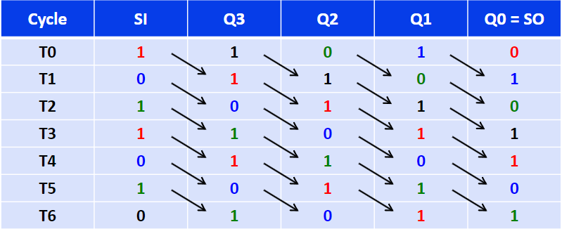
- Allows data to be shifted from each flip-flop to its neighbour
- All bits are shifted simultaneously at the active edge of the clock
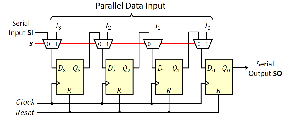
Parallel-In Serial-Out Shift Register
- Two control functions:
- s = 0 → shift (works like above)
- s = 1 → load data (update D for each flip-flop)
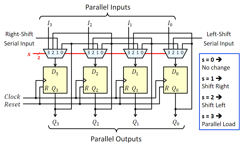
Universal Shift Register
- Four control functions:
- s = 00 → no change in value
- s = 01 → shift right (right-shift serial input)
- s = 10 → shift left (left-shift serial input)
- s = 11 → parallel load 𝑛𝑛 input bits
Multi-Function Arithmetic Logic Unit (ALU)
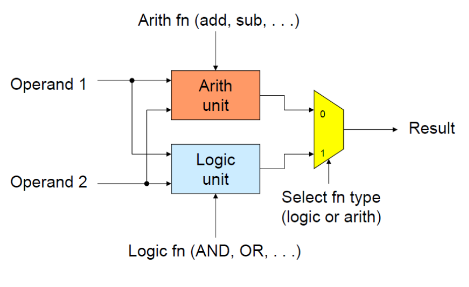
- An ALU can do arithmetic and logical operations