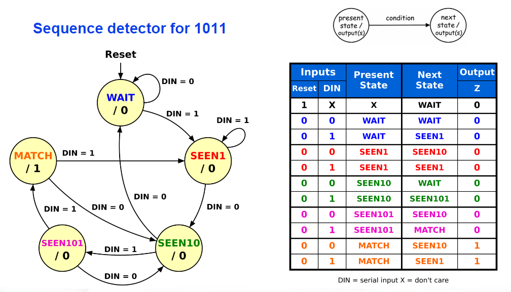
A state table (also known as state transition table) is a tabular representation of a FSM’s behaviour. Each row specifies the next state and output for one combination of present state and inputs.
| Present State | X | Next State | Output |
|---|---|---|---|
| EVEN | 0 | EVEN | 0 |
| EVEN | 1 | ODD | 0 |
| ODD | 0 | ODD | 1 |
| ODD | 1 | EVEN | 1 |
It describes the same information as a state diagram, and is used as a more direct source to work from when designing sequential circuits.
Quote bq
An
X(don’t care) can appear in a input column when a transition doesn’t depend on that particular input.
Excitation Tables
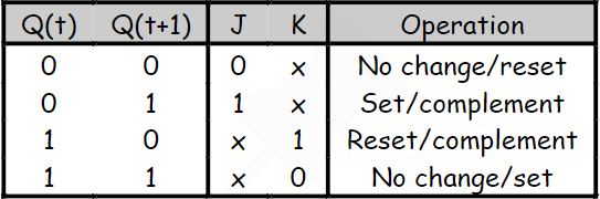
From a state table, we can build an excitation table that lists the necessary inputs required for a sequential circuit element, such as a flip-flop, to transition from a current state to a desired next state.
Summary bq
Excitation tables are used to help implement our state table logic into an actual design.
await dv.view("Scripts/topic-backlinks");