A state diagram is a graphical representation of an FSM’s behaviour. Each circle represents a state, and each labelled arrow shows the input condition that causes a transition between states.
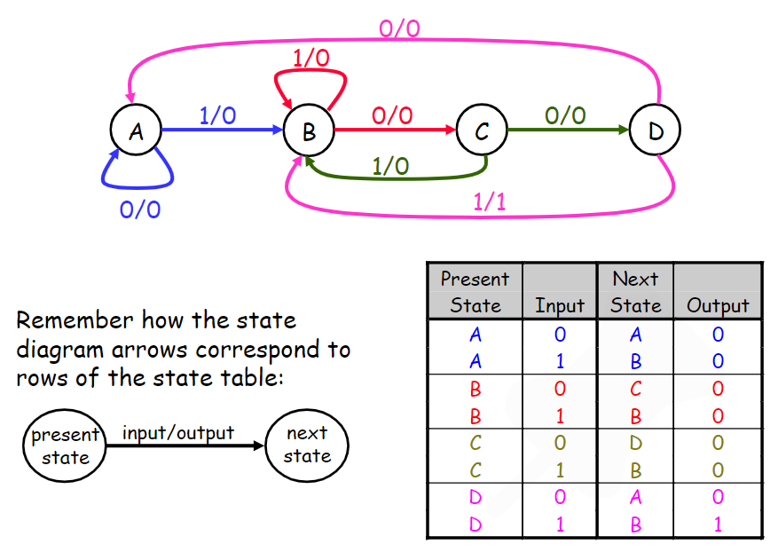
Output Notation
Notation depends on the machine type:
- Moore — output written inside state bubble:
state / output- Mealy — output written on arc (as above):
input / output
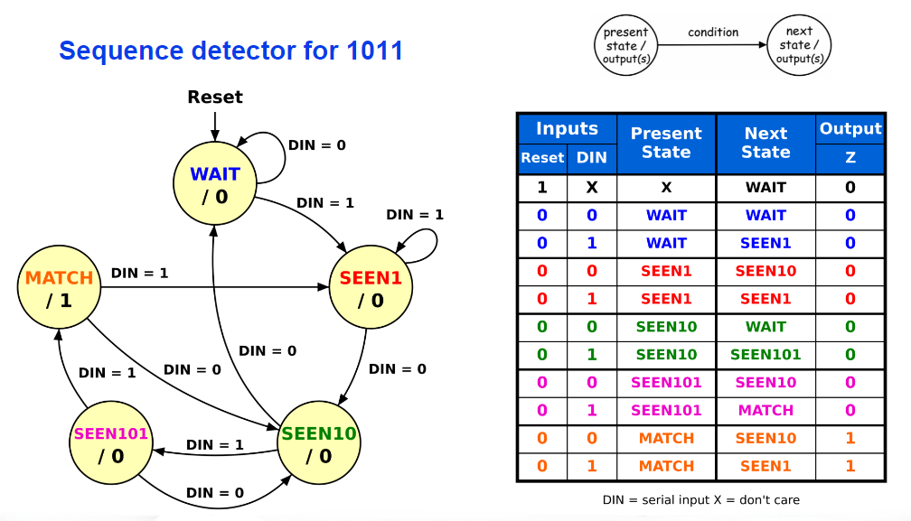
A state diagram describes the required behaviour without specifying how the circuit will be implemented. It is an alternate representation to a state table, but carries the same information.
await dv.view("Scripts/topic-backlinks");