DC Motors
- Motor converts electrical energy into mechanical energy
- Generator converts mechanical energy to electrical energy
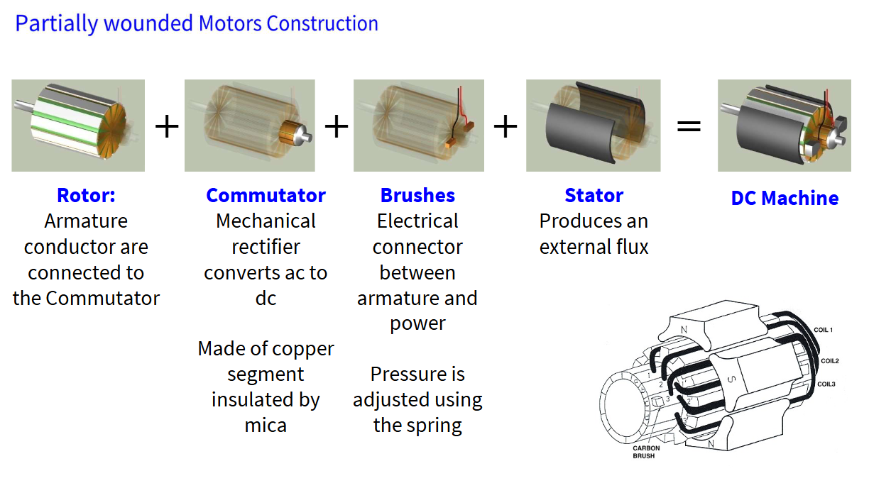
- Rotor rotating part of motor
- Carriers wire-wound coils
- Coils create Lorentz force when energised
- Stator stationary part of motor
- Holds magnets that create a fixed field
Circuit Model of DC Motors
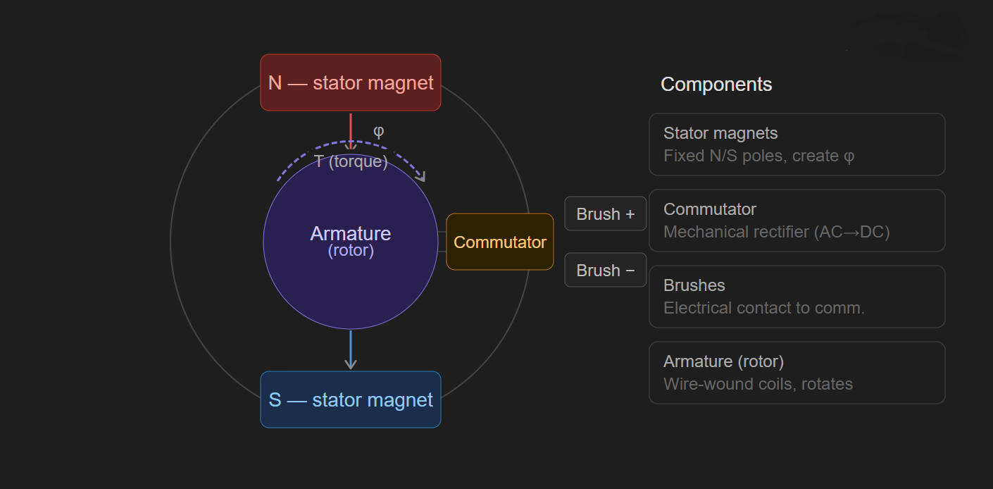
The conduction path of the motor looks like:
- Brush -> commutator -> coils -> commutator -> brush
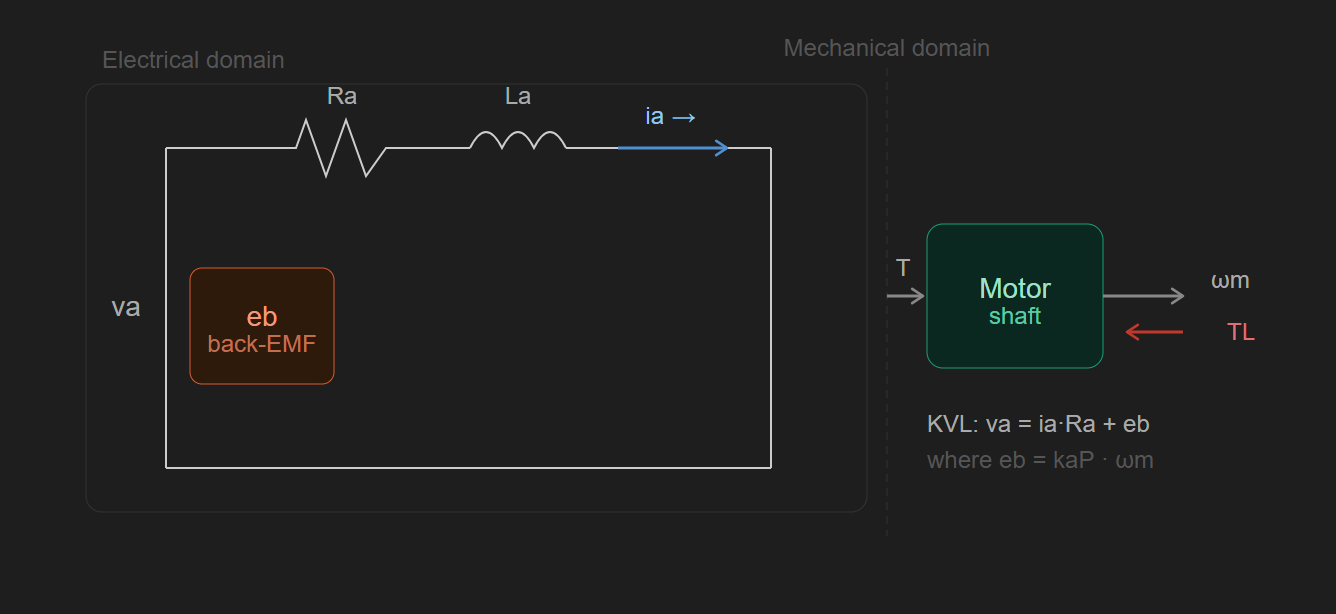
There are only three important properties we need to model:
- armature resistance
- i.e. the wire resistance in the coils
- armature inductance
- back-EMF
- Generated by coils spinning in magnetic field
- Opposes the applied voltage (Lenz’s law)
DC Steady-State
From Lenz’s law:
In steady-state, inductor -> short circuit
- Thus, we are left with two equations:
- Electrical:
- Given by KVL
- Mechanical:
- From torque equations
- Electrical:
For an ideal motor, torque constant and armature constant are equal
Analogue Speed Control
Constant voltage drive
- Motor won’t move below a threshold voltage
- Minimum voltage:
- This is due to static friction
- Then, suddenly jumps to speed above the minimum
- Thus, some speeds are inaccessible from a stationary start
- Think of pushing a heavy box in real life
Constant current drive
- Better torque control since
Digital Speed Control
Pulse-width modulation (PWM)
- Voltage is either zero or a maximum value
- Ensures voltage is always above threshold value
- Motor drive voltage is periodic
- On for time
- Off for time
- Total period is
- Duty cycle is
- If is sufficiently small, motor movement is continuous
PWM is the solution to the static friction problem of constant voltage sources; we can achieve any speed with good control
End of Unit!