Overview
- There are 10 fundamental methodologies used for circuit analysis
- This page is currently unfinished with only the first 6 methods
- These are must know concepts for engineers
- This is a summary cheat-sheet to look upon for help
1. Voltage Division (VD)
-
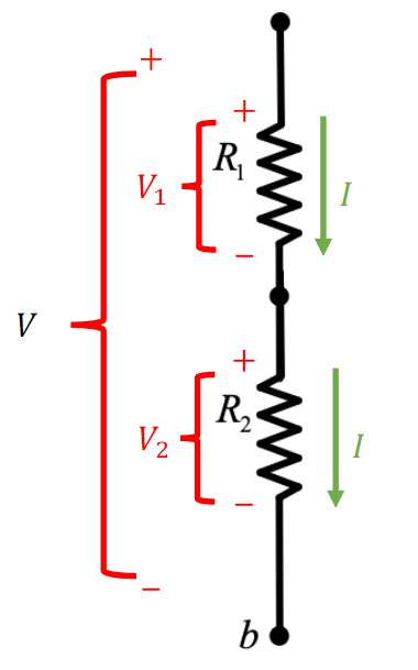
How do we find voltage across and in series?
-
Total current is:
Applying Ohm’s Law we get:
For the voltage drop across the th resistor in series, we get:
2. Current Division (CD)
-
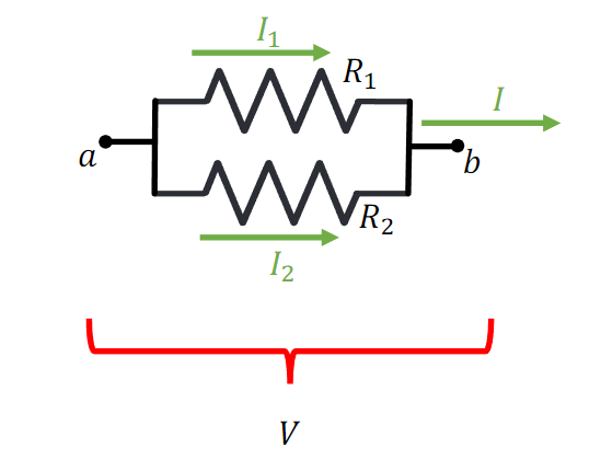
How do we find current through and ?
-
Total voltage is:
For the current drawn by the th resistor in parallel, we get:
3. Kirchhoff’s Current Law (KCL)
- If conductors connect to a node, then at this particular node, the sum of input and output currents is zero
- Convention:
- Current flowing into node is positive
- Current flowing out of node is negative
4. Kirchhoff’s Voltage Law (KVL)
- The sum of voltages around a closed loop is zero
- Convention:
- Voltage rises ( -> ) have positive sign
- Voltage drops ( -> ) have negative sign
5. Node-To-Datum (NTD) Analysis
- We describe a voltage at each node using a reference voltage
- This reference is known as a node-to-datum voltage
- Each node is described having a difference in potential compared to the node-to-datum voltage
Steps for NTD:
- Identify all nodes in a circuit and select node as reference node, voltage at reference node is assumed to be ->
- If a voltage source is connected between reference node and non-reference node -> nodal voltage = voltage from voltage source
- Apply KCL to remaining non-reference nodes + use Ohm’s Law to express unknown branch currents in terms of node voltages
- Solve resulting simultaneous equations to obtain unknown node voltages
Resistors are passive elements, that means if a current moves across a resistor with resistance of Ohms and moves from node A to node B, node A is considered the () end and node B is the () end:
Node-To-Datum: Supernodes
-
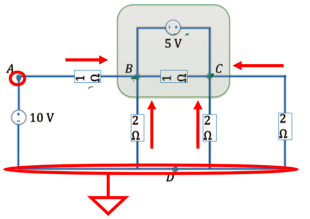
You cannot use NTD to solve circuits where a voltage source is connected between two non-reference nodes
-
The two non-reference nodes form a signal supernode
- Within a supernode, voltage difference between two nodes inside are equal to voltage supplied by the voltage source
In the example above: , this can be subbed back into our KCL equations to solve them
6. Mesh Analysis
- A mesh is a closed loop that cannot contain any smaller closed loops inside of it -> the smallest closed loops possible
- The circuit above has four meshes, one in each square
- We use a theoretical mesh current to represent a current circulating (clockwise) around the mesh
- Current does not exist in reality and is only used in analysis
The total current through a component at the intersection of two mesh elements is the sum of both mesh currents
- Mesh current -> () if current through element also flows in the same direction, otherwise mesh current -> ()
Steps for Mesh Analysis:
- Choose a set of mesh currents
- Write KVL equations around each mesh to obtain set of equations in terms of the mesh currents
- Solve equations to obtain mesh currents
- Determine individual element currents and voltages from this
7. Superposition
- This technique applies only when your circuit system is linear
- Given is an output of a system with input , the system is said to be linear if:
- -> homogeneity
- -> additivity
Capacitors and inductors are considered linear elements
- The only non-linear elements in this unit are dials and optional amplifiers
- A circuit is linear if it contains only linear elements
Steps for superposition analysis:
- Keep only one independent source active, turn off other sources
- Replace off voltage sources -> short circuits
- Replace off current sources -> open circuits
- Repeat step 1 for each independent source
- Determine the contribution of each source on the given resistor and then sum to get the total
Read walkthrough in slides
-
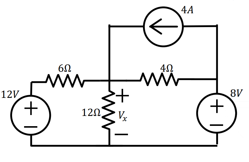
Lets use this circuit as an example:
-
We need to find the value of
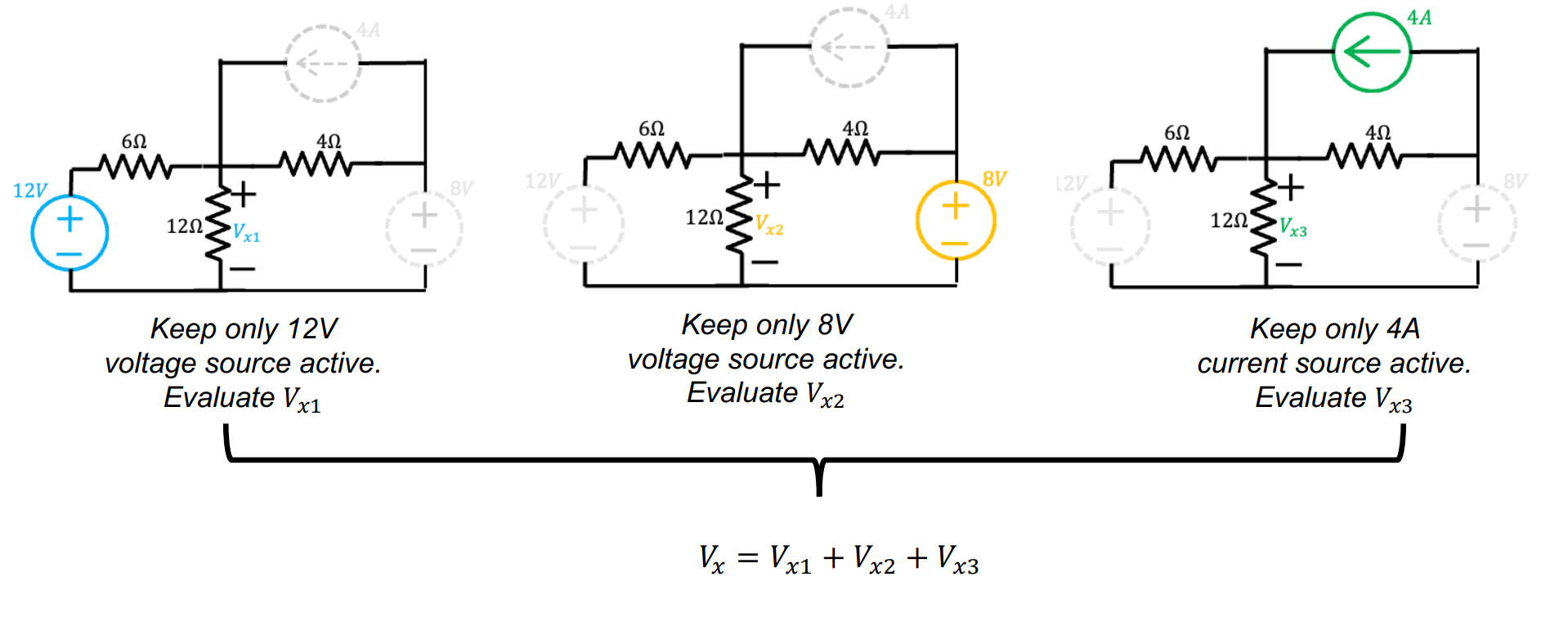
-
Example of replacing independent sources:
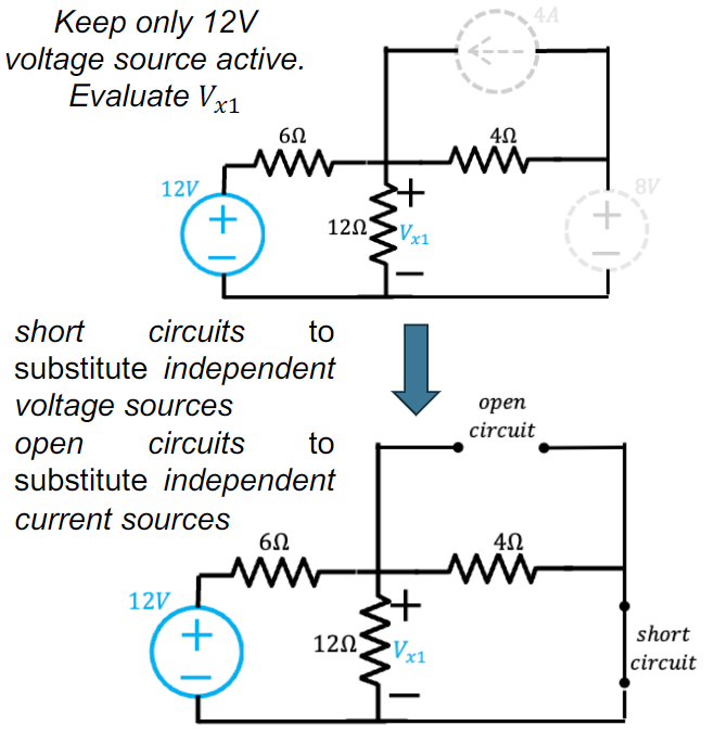
- Here, we can now use NTD to solve for
- In other cases, you can use whichever analysis technique is most efficient (e.g. VD, CD, NTD, Mesh)
- Repeat for each independent source
- Here, we can now use NTD to solve for
8. Source Transformation
- Consider same network “A” is attached to two separate sources
- Both sources have same source resistance
- How can we get both sources to produce the same current and voltage into network A?
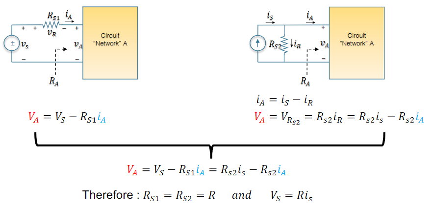
If the equation is met → both sources are identical
-
Knowing this, we can transform a voltage/current source into its alternate form in our circuit:
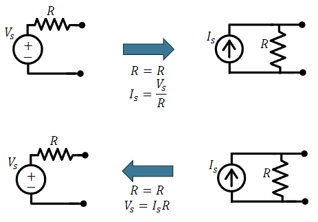
-
This is useful because we can switch a resistor from being in series and parallel in order for us to combine resistors → see slides
Source transformation is key for simplifying circuits
Equivalent Circuits
If we are interested with only one part of the network, the remainder of the network may be replaced by a simple equivalent network
- Aim: Take a complex circuit and replace it with a similar equivalent
We can replace our complex circuit with either:
- Thevenin: Voltage source with resistor in series
- Norton: Current source with resistor in parallel
These two simple networks are the same as our practical sources!
9. Thevenin Theorem
- Thevenin Theorem replace network with voltage source and resistor in series
- Network must be linear
- Network only contains voltage/current sources + resistors
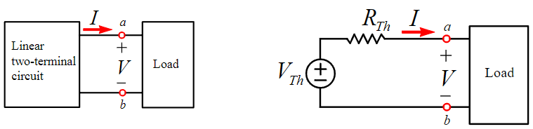
- Theorem can be expanded to fit other linear elements
e.g. capacitors and inductors
Find → equivalent voltage is the voltage difference across the open terminals with the load removed
Find → replace voltage sources with short circuits + current sources with open circuits, calculate between open terminals with load removed
Remember, a chain of resistors connected to the same node at both ends of the chain with no source (as we have removed them) do not contribute to → look for resistors that are connected in chain with the open part of the circuit
The new circuit is known as the Thevenin equivalent circuit
10. Norton’s Theorem
- Norton’s Theorem replace network with current source in parallel with resistor
- Network must be linear
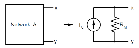
Find → replace load with short-circuit, the current flowing through short-circuit is
Find → replace load with open terminals & turn off all independent sources, calculate between open terminals with load removed