AVR is a family of microcontrollers originally developed by Atmel in 1996. They are 8-bit RISC single-chip microcontrollers based off modified Harvard architecture.
AVR microcontrollers are used numerously as embedded systems. They are commonly used as the chip for Arduino boards.
AVR Programming Tools
For programming an Atmel AVR processor, such as an Arduino Nano 3.0 – Atmel ATMega 328P, we can use several tools:
Assembly Programming
Use Atmel Studio 4 (or higher)
Upload programs using ‘nano’ batch file (avrdude)
C Programming
Use WinAVR
Upload programs using ‘nano’ batch file (avrdude)
Arduino Core
Install the Arduino tool
Compile and upload programs from Arduino tool
Machine Code
Programming of a computer system can be broken into three levels:
Machine Code — direct execution
Assembly Language — human-readable mnemonics that map 1:1 to machine instructions, machine dependent
High Level Programming Language — machine-independent, needs translation by a compiler
Machine code is the lowest level a computer can be programmed in. It involves specifying the program in byte codes corresponding to the CPU’s instruction set. For example, 05A1 -> LOAD mem[A1]. The instruction format is machine dependent and cannot be ported.
Programming in machine code is difficult and error-prone and therefore is not used in practice. Instead, we use name abbreviations that make programming easier (e.g. ADD for adding). This is known as assembly language and is highly preferred over writing direct machine code.
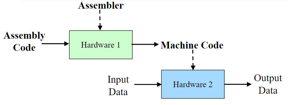
Assembler
Assembly language requires a translation tool known as an assembler to translate our abbreviations into the corresponding machine code.
An assembler is machine dependent and translates code line-by-line.
AVR Assembly
Each line in AVR assembly is made up of four parts:
Label: COMMAND operand1, operand2 ; comment
Label: — an optional named address, used as a branch target
Command — the opcode
Operands — arguments to operate on
Comment — should describe what process accomplishes
Two Operand Instructions
With two operand instructions, the result overwrites the first operand (ADD R16,R17 → R16 := R16+R17).
Each instruction is 16-bits in size. The data is typically split into three parts:
Opcode
Destination Register — operand1
Source Register — operand2 (if applicable)
The size of these parts can vary depending on the type of instruction. For example, a single operand instruction only needs 5-bits to select a destination register, thus it has 11-bits to represent more opcodes.
A two operand instruction only has 6-bits to contain its opcode. Thus is more limited in the number of potential operations for two operands.
SBR / CBR : Set bit in register / clear bit in register
SBI / CBI : Set bit in I/O register / clear bit in I/O register
Stack & Subroutines
PUSH / POP : Stack operations
CALL / RET : Subroutine jump / return
AVR Immediate Operations
Some operations known as immediate operations load a hardcoded number straight out of the program code instead from a specified address.
For example: LDI R16, 100 -> R16 := 100
These operations only work with R16-R31. This is because 8-bits are dedicated to the constant, leaving only 8-bits for the opcode and register ID.
Using 4-bits for the register ID is not enough to represent all 32 registers. Instead, we limit the selected register to be between R16-R31 by setting the source bit 4 to 1 (0000 -> 10000).
The ‘immediate’ property is indicated by the I following most standard commands (e.g. LDI, SUBI, ANDI, CPI)
AVR Operands
Each operand can be a constant, register or a memory value/location. Registers are labelled by number from R0 to R32 for an 8-bit microcontroller. Memory values are usually specified by a label (variable name) or a pointer register pair (X, Y, Z).
Constants need to have a prefix to indicate what type they are. Decimal is the standard type, and has no prefix. Hexadecimal (Base-16) is prefixed with 0x or $. Binary is prefixed with 0b. Standard (ASCII) characters must be wrapped in single quotes.
Decimal
Hexadecimal
Binary
Character
10
0xD7 or $D7
0b0110
’Z’
AVR Registers
AVR architecture uses 32 working 8-bit registers (R0...R31) connected to the ALU. The CPU can pull two values from any of these registers, perform an operation and write the result back in a single clock cycle.
The last six general-purpose registers (R26 through R31) also double as three 16-bit pointer/index registers by pairing up. This is because 8-bit registers alone are not large enough to hold memory addresses, which are usually larger than 255 bytes.
X Pointer: R27 (High byte) + R26 (Low byte)
Y Pointer: R29 (High byte) + R28 (Low byte)
Z Pointer: R31 (High byte) + R30 (Low byte)
The high byte register holds the left 8-bits while the low byte register holds the right 8-bits. Together, they can store a 16-bit number.
The Status Register
The 8-bit status register contains flags that store the outcome of the most recently executed ALU instruction:
C (Carry): Indicates an arithmetic overflow/carry.
Z (Zero): Set if the result of an operation is zero.
N (Negative): Set if the result is negative.
V (Overflow): Indicates a two’s complement signed overflow.
S (Sign): Exclusive-OR of N and V.
H (Half Carry): Indicates carry between bit 3 and 4.
T (Bit Transfer): Temporary storage for single-bit operations.
I (Global Interrupt Enable): Master switch to enable/disable system interrupts.
There is also 64 special registers for control and I/O.
Some key special registers include:
SP -> stack pointer
SMCR (Sleep Mode Control Register) -> configures power-saving modes
JMP next ; always jump ...next: ADD ... ; destination
Conditional branch:
CP R1,R2 ; compare reg.BREQ next ; branch if equalCLR R7 ; else do this ...next: ADD ... ; destination
The conditional branch works by using flags from the status register. For example: a Z flag, (i.e. a zero) will mean that the condition is false and no branching will occur. This is also how a CPU memorises the result from the proceeding operation.
The most important flag conditions are:
Z — zero
N — negative
C — carry
V — overflow
Important Branch Commands
BREQ / BRNE : Branch if equal (=0) / not equal
BRGE / BRLT : Branch if greater or equal / less than (signed)
BRPL / BRMI : Branch if plus / minus
BRCS / BRCC : Branch if carry set / clear
BRVS / BRVC : Branch if overflow set / clear
If a conditional branch fails, the program just moves to the next instruction step (PC := PC + inc).
Branching is the standard way to implement if-then-else functionality:
	  CPI  R16, 10
	  BREQ then
else: SUB  R16, R2
      JMP  next
then: ADD  R16, R1
next: …
AVR Addressing Modes
All assembly commands need operands and there are several ways you can declare an operand. These methods depend on the type of operand you want to declare and where it is stored.
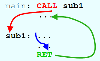
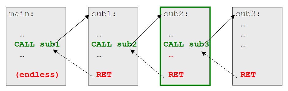
The command CALL is similar to JMP, however it preserves the current program counter on stack so that execution can return later using RET (return from subroutine).
For the CALL command to work, we need to store the address of the main program somewhere so we can jump back upon RET. If we stored this address in a register, than we would run into issues upon calling a subroutine within a subroutine.
Instead, we must use a stack which holds all the addresses of the parent program in RAM for later. We have a dedicated stack register (SP) which holds a RAM address that points to where the last return address is stored.
Note that the SPincrements by 2 bytes as the PC counts in 2-byte words. On most architectures, the stack grows downwards in memory as it takes up the last section of RAM. Thus, CALL decrements SP by 2 and RET increments SP by 2.
RET pops the address from the stack and puts in the PC for us to jump back. The SP then increments to leave it pointing at whichever address was pushed previously.
A closeup look at CALL and RET:
CALL: 1. PUSH PC+2 1.a Mem[SP] <- PC + 2 1.b SP <- SP - 2 2. PC <- addressRET: 1. POP PC 1.a SP <- SP + 2 1.b PC <- Mem[SP]
Save and Restore Registers
Registers are a shared resource, used by the main program and subroutines. As such, you don’t want a subroutine to override data stored in a register that your main program is using.
We can address this issue by pushing register data onto the stack and then popping it at the end of the subroutine’s execution.
For example, if a subroutine uses R1 and R2:
mysub:  PUSH R1 ; save registers
        PUSH R2
		...     ; subroutine function
        POP R2  ; restore registers
        POP R1  ; in reverse order
        RET
You must POP registers in reverse order, otherwise the data they stored will swap positions.
AVR Input/Output Ports
Traditional processors have a fixed number of inputs and outputs.
Modern processors on the other hand can configure each I/O line to either be input or output.
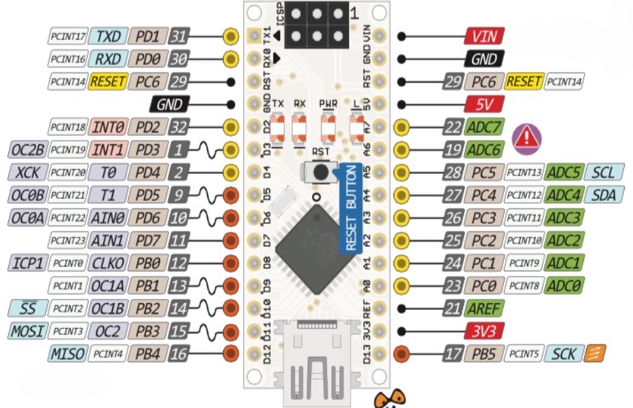
Pins are grouped into 8-bit registers called ports. The ATmega328P has bidirectional Ports B, C and D.
Not all the port pins are accessible however, (PB6, PB7 and PC7) and some ports have multiple functions such as PC6 (reset), PD0 (RX) and PD1 (TX) which should not be used for general I/O.
Each port uses three specific 8-bit registers to control its behaviour:
Register
Name
Function
Assembly Instruction
DDRx
Data Direction Register
Configure pin direction
OUT DDRD, R16
PORTx
Port Data Register
Set output pin values
OUT PORTD, R16
PINx
Port Input Pins Address
Read pin input
IN R16, PINB
Before reading or writing, the DDRx register must be initialised. Writing 0xFF sets all 8 pins to outputs, while 0x00 sets all pins to input. You store the I/O instruction inside your declared DDRx register (R16 in table above).