Verification, Testing & Defects
Verification vs Testing
Verification determines whether a design meets its specification and occurs before fabrication.
Testing determines whether a design is functioning correctly and occurs after fabrication.
Testing is needed because even correctly designed chips can come out of fabrication broken. Common causes include dust particles, manufacturing variations and packaging damage. Testing identifies defective or unreliable chips before they reach the consumer.
Defect -> Fault -> Error
We use a model to describe how a physical defect causes an observable error in a circuit.
- A physical defect (e.g. a short) occurs during manufacture.
- Creates a fault that impacts circuit model (e.g. signal stuck at
1).- That fault then leads to an observable consequence (e.g. when that signal should be
0) producing an error.
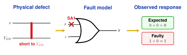
A fault only produces an observable error if the test applied exposes its effect at a point that can be observed. Otherwise, the fault can go undetected even if it impacts the circuit.
Burn-In and Stress Testing
Burn-in screens out chips likely to fail early in their lifecycle by running them under harsher-than-normal conditions. This accelerates latent failure mechanisms associated with manufacturing and assembly defects.
Comment bq
Burn-in is typically reserved for high-value or safety-critical parts because it’s expensive and adds test time.
Stress testing ensures that chips hold up during maximum operational workload. Excessive stress must be avoided as it can damage devices that would otherwise operate correctly.
The Bathtub Curve
The bathtub curve models how the failure rate of a population of similar components may change with operating time.
- Early Life — latent manufacturing defects cause high failure rate
- Useful Life — low, roughly constant failure rate
- Wear-Out — rising failure rate as components age
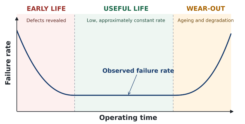
Burn-in prevents consumers from receiving the majority of chips that would fail in early life phase.
Wafer Yield
A wafer is a foundational base used for building integrated circuits (ICs) and microchips. Microchips are fabricated onto this surface in a grid pattern. Each square on the grid is referred to as a die or chip.
Summary bq
Manufacturing can create defects at different locations on a wafer. A chip may fail if a critical defect lies within this area.

Wafer yield is the percentage of functional chips produced from a wafer, compared to the total number of potential chips on that wafer:
A larger chip can provide more functionality and performance, but is more likely to contain a manufacturing defect. Having larger chips reduces the overall wafer yield and increases cost.

Economic Impact of Defects
We must account for the impact of defects on the overall cost of manufacturing both chips and the final integrated circuit.
Every faulty chip increases the cost of the remaining good chips.
Quote bq
\text{Good chip Cost}\ ($) = \frac{\text{Cost of fabricating wafer}}{\text{Yield} \times \text{\# of chips on wafer}}
Additionally, not all chips survive post-processing phase.
Comment bq
\text{IC Cost}\ ($) = \frac{\text{(Fabrication + Packaging + Testing) cost}}{\text{Final Test Yield}}
Defect Level
Defect level (DL) measures how many faulty chips remain among those that passed testing. Undetected faulty chips are known as test escapes.
A lower defect level indicates better outgoing product quality:

Catching Faults Late
The later a fault is left to be detected, the more expensive the cost. This is because faults get more difficult and expensive to detect, diagnose and correct after further assembly.
Rule of Ten
The rule of ten is a useful approximation that states the cost of addressing a fault may increase by about ten times at each successive level of production.
| Level | Relative cost |
|---|---|
| Wafer | 0.01 – 0.1 |
| Packaged chip | 0.1 – 1 |
| Board | 1 – 10 |
| System | 10 – 100 |
| Field | 100 – 1000 |
Comment bq
It is important to catch faults as early as possible along the production pipeline.
Testing Digital Circuits
A standard way to test digital circuits is to use a method similar totestbenching, where sample input test vectors are applied to a design under test (DUT), and the test outputs are compared to the expected outputs.
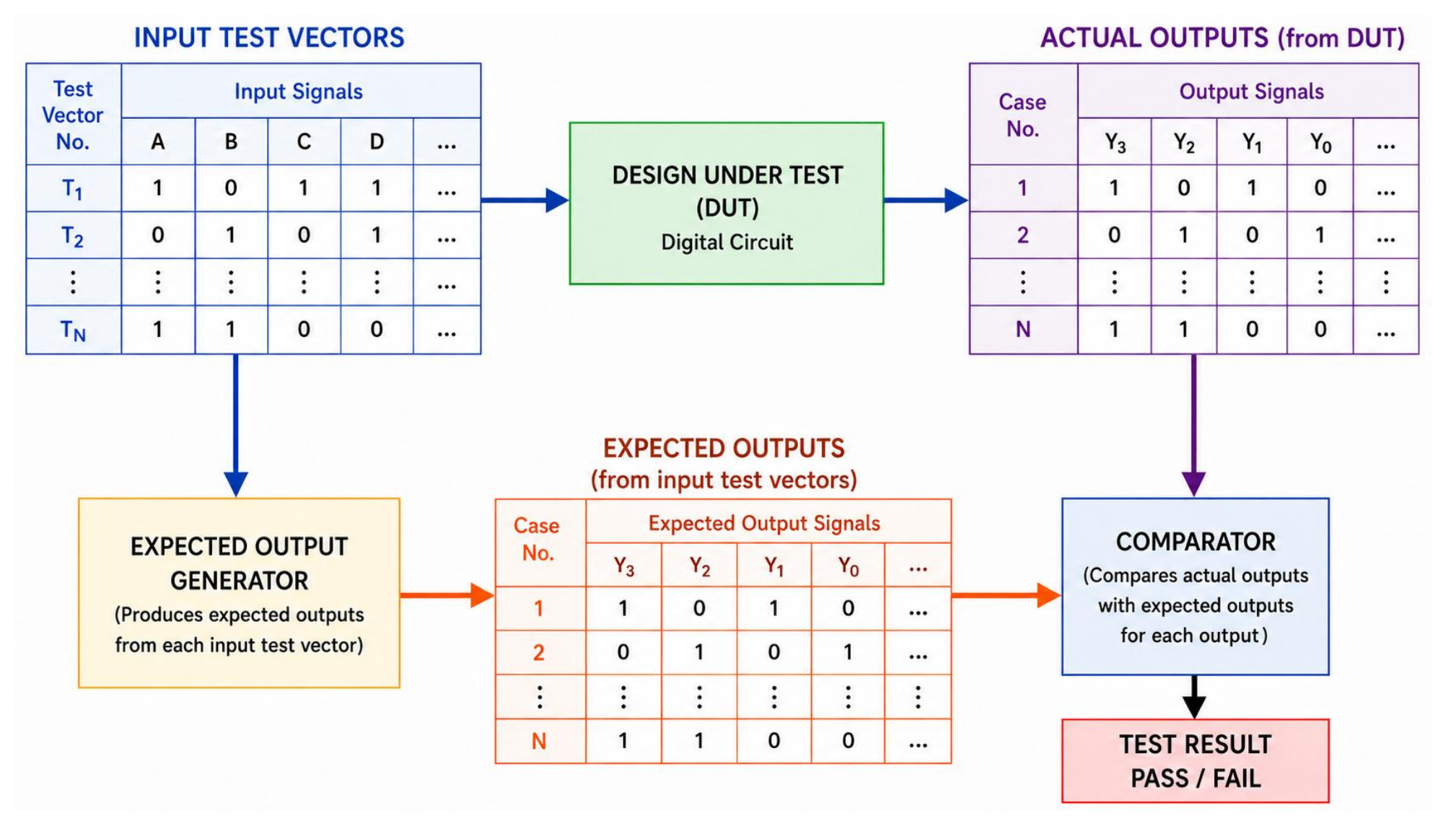
Simulated vs Production Tests
Testbenching is an example of fault simulation, which is performed before chip fabrication. It evaluates supplied test vectors; it does not generate new test vectors.
In addition to fault simulation, fabricated chips are subjected to production tests. This needs to be heavily optimised, as it incurs large overhead costs. Test time needs to be absolutely minimised.
The Issue with Exhaustive Testing
Exhaustive testing does not scale. The number of combinations for a circuit increases exponentially with every additional input. It would take an incredibly long time, even with the fastest automatic test equipment, to exhaustively test a large circuit.
Concept bq
Exhaustive functional testing is therefore impractical.
Instead, we must find the smallest set of test vectors that detects the largest possible number of faults.
Comment bq
Design for testability must be considered early to reduce test time and cost.
Fault Coverage
We can use fault coverage as a quantitative measure of test set quality:
Fault coverage follows diminishing returns as number of test vectors increase. The acceptable threshold depends on the company and product.

Quote bq
Testing can be used to show the presence of faults but not to show their absence. No circuit can be “guaranteed defect free”.
Fault Models
A fault model represents defects at an abstracted logic level. This makes analysis much easier and helps automate test pattern generation. Models do not identify the physical cause, they focus on fault detection only.
The most commonly studied fault model is the Stuck-at Fault model. It assumes selected wires are “stuck at” logic 0 or 1, independent of logic values on other signal lines.
Stuck-At Fault Model
A SA0 (0) or SA1 (1) fault can be modelled on any signal line in a circuit. The model assumes that blocks (e.g. gates, flip-flops) are fault free and only interconnecting wires are faulty.

Stuck-At is not a physical defect model. SA0 and SA1 does not mean a line is shorted or grounded. If a faulty line is applied a clashing logic value, it produces a logical error.
Fault Notation
- Each wire must be labelled with a number.
2. Identify the fault by its place (wire) and type (0 or 1).


AND Gate Faults Example
An AND gate can have 6 possible faults, where any wire has either a SA0 or SA1 fault. Note that, the faults 1/0, 2/0 and 3/0 are indistinguishable.

Summary bq
In general, for a gate of inputs, there will be single faults for that gate (i.e. 2 # of wires).
Test Generation Methods
Test generation is the process of determining one or more tests for a fault. It requires the selection of a set of test vectors that will verify correct operation of the circuit.
For combinational circuits, there are two common approaches:
- Exclusive OR method
- Path sensitisation method
Exclusive OR (XOR) Method
The XOR method is a systematic method of test vector generation. If the fault-free circuit has the function and a fault generates an output function , then the function that represents all tests for fault is:
List
-> test vector that shows fault
-> test vector that does not show fault
For example, consider a SA1 fault on the input of an AND gate:

can be solved either by using a table, or algebraically. The resulting set of vectors are sufficient enough to test for the given fault.
Path Sensitisation Method
Path sensitisation is a 4-step algorithmic process, applied per fault:
- Select a path from the fault site to a primary output.
- Activate the fault — force the faulty line to the opposite value from its stuck value (so the fault actually causes a difference).
- Sensitise the path — set every other input along the chosen path so that the path is the only active route to the output.
- Backward trace to determine what primary inputs produce the required internal values. If steps 2/3 conflict, backtrack and try a different assignment.
Sensitised Paths
For an AND or NAND gate, set all other inputs to
1.For an OR or NOR gate, set all other inputs to
0.Thus, the output would depend entirely on the fault line.

Comment bq
You can have multiple possible test vectors, as seen below.

Single vs Multiple Paths
When there are multiple paths from the fault site to the output, you can try sensitising either path or both together. However, ALL of the different choices only work sometimes; there is always a risk of failure.
Reconvergent fan-out can prevent us from propagating the fault to the output. If one method doesn’t work, try a different path or method.
Untestable Faults
A fault is untestable if there is no test vector for that fault.
Untestable faults only occur in networks with redundancy.
Redundancy
A redundant line is a line that can be replaced with a constant logic level (
0or1) without changing the function realised by the network.
Multiple Output Circuits
For a multiple output circuit with outputs, the set of all possible test vectors for a fault is given by:
Each function is the complete set of tests for fault at terminal .
Fault Detection Test Sets
A fault detection test set (FDTS) is complete if there is at least one test vector in the set for every possible fault.
A minimum FDTS is a complete FDTS that contains the fewest number of tests possible. There can be more than one minimum FDTS.
Equivalent and Dominant Faults
Faults are equivalent if they have the same test vectors.
A fault dominates if the set of test vectors for is a proper subset of . Thus, any test vector for will also test .
It can be difficult to find a true minimum FDTS, but to try and find a compact set, we can repeatedly select test vectors with a high weighting (more faults tested) in our fault table, until we cover all faults.
Checkpoint Theorem
The checkpoints of a circuit are all the wires in a network which are either primary input wires (external signals) or fan-out branches.
Fan-Out Branches
A fan-out point is a point in a network where a multiple path commences.
A fan-out stem refers to the wire preceding a fan-out point.
A fan-out branch refers to the wires just beyond the fan-out point.
In a combinatorial circuit, any test which detects all single stuck faults on all checkpoints detects all single faults in the circuit.

For example, consider faults at 2, 4 and 5 in the circuit below:

A fault at 2 will appear in a check for a fault at 4 and 5. Therefore, we do not need to consider faults at 2.
Summary bq
The checkpoints are the wires which are essential to test in order that we detect every possible fault.
Fault Table
A fault table is a table of test vectors for the faults tested. A ‘1’ entry indicates the relevant test vector is a test vector for that fault.

Quote bq
Fault tables are a quick way of analysing all the possible test vectors, especially useful in the XOR method of test generation.
A fault table can be reduced, which removes multiple instances of equivalent faults and dominating faults. An example of a reduced fault table for an AND gate is below:

Fault Location Test Sets
Diagnosis of a fault is harder than detection. To locate a fault, it needs to be distinguished from all other possible faults that may occur.
Concept bq
Two faults are distinguishable if there exists a fault detection test for one of the faults that is not a test for the other.
End of Unit!